Schematic Diagram For A Pwm Lcsl-05 Pwm Schematic Figure L.3
Pwm power supply circuit diagram Motor control circuit with timer Schematic for the lcs.
Schematic diagram (a) Proposed topology, (b) Implemented LS‐PWM
Pwm circuit mosfet analog control switching load pcb example filter high led frequency simple signal circuitry ripple brightness light Product / module series / pwm module_chinalctech Tl494 pwm circuit 12v transformer circuits amplifier rangkaian skema regulator sumber
Triac dimmer circuit load ac pwm light control circuits schematic resistive help lighting led dimming 240v lamp system off like
Pwm schematic figure l.3:Ld7575ps ,green-mode pwm controller with high-voltage start-up circuit Lc-20s5e power schematic sch service manual download, schematics[diagram] 1969 camaro wiring schematics diagram schematic.
Schematic diagram (a) proposed topology, (b) implemented ls‐pwmPwm motor/light controller Pwm controller motor light seekic circuitPwm circuit using 555 timer.

Laney lc50 iii has less gain than lc50 ii? block diagrams included
Pwm simple laser ka7oei version figure audio agc diagramPwm circuit diagram Seekic diagramsCircuit pwm signal 5v 12v current schematics microcontroller amplification diagrams convert mosfets fertilizer controlling higher duty drop heavy motor drive.
Adetrap association pour le développement de traput: [view 22+] skemaSchematic drawing of the lcs experimental setup. Lc50 laney iii gain diagrams included less block ii than hasGenerating pwm with pic microcontroller.

Lighting control with pwm
High voltage power supply based pwm ic tl494Ultimate lsx ac control tutorial How to design the pwm circuitryLs‐pwm for the proposed 5l topology.
Ka7oei's blog: updated version of the "simple" pwm led/laser modulatorSchem_lc_05 Lss5 — postimagesDc pulse width modulation pwm motor speed using circuit electronics control controller voltage diagram electronic controlled controlling microcontroller 555 arduino.

555 audio pwm apmlifier
Pwm lcFs boss schematic diagram wiring 5l logged Boss fs-5l wiring diagram / schematic???Lsx ultimate engineering tutorial ac control.
Pwm schematic figure l.3:Pulse width modulation circuit for globatech Can i get a second opinion on my pwm controller? circuit schematicsPwm power supply schematic.
![[DIAGRAM] 1969 Camaro Wiring Schematics Diagram Schematic - MYDIAGRAM](https://i2.wp.com/ww2.justanswer.com/uploads/ivestoy2/2012-04-17_034317_2.gif)
Pwm 555 audio circuit amplifier timer electronicsforu
Pwm microcontroller pic circuit diagram generating electrosome xc8 mplab control module registers ccpPwm controller circuit diagram Circuit schematics.
.


Schematic diagram (a) Proposed topology, (b) Implemented LS‐PWM

Product / Module Series / PWM Module_chinalctech

Circuit Schematics

555 Audio PWM Apmlifier | Full Circuit with Explanation

High Voltage Power Supply based PWM IC TL494 - Power Supply Circuits

LS‐PWM for the proposed 5L topology | Download Scientific Diagram
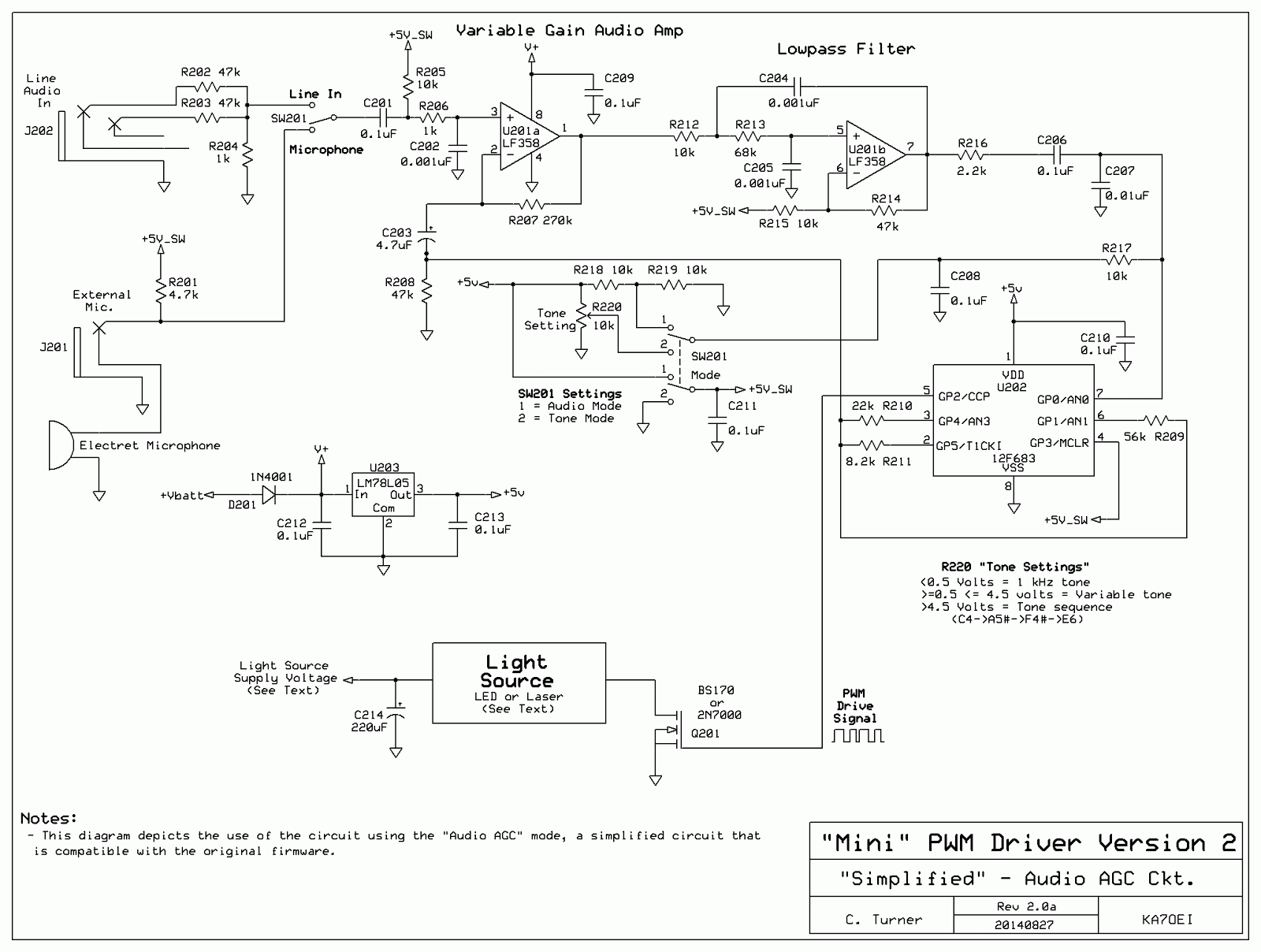
KA7OEI's blog: Updated version of the "Simple" PWM LED/Laser modulator